English
 русский
 Español
 عربى
عربىWhat are the components of brass motorized valves?
What are the components of Brass Motorized Valves?
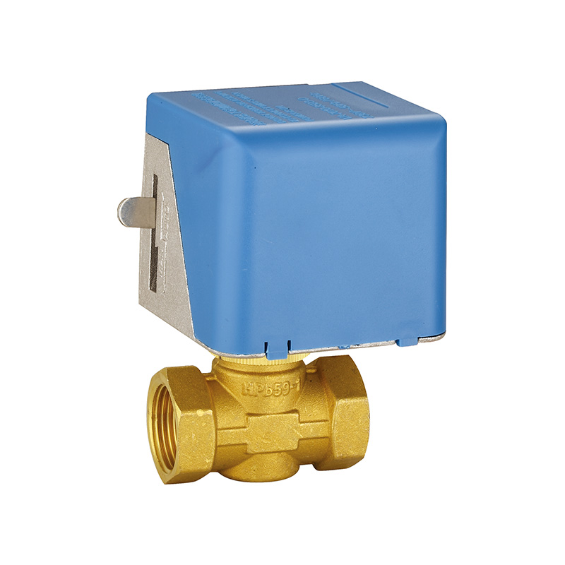
A brass motorized valve is an assembly of two primary subsystems: the valve body and the actuator.
Brass Valve Body: This is the fluid-handling component, typically made from dezincification-resistant (DZR) brass alloy. It contains the inlet and outlet ports, the valve seat, and the obturator (the part that opens or closes the flow path, such as a ball, disc, or plunger).
Stem or Spindle: This is a metal shaft that connects the obturator inside the valve body to the actuator. Its rotation or linear motion is what opens or closes the valve.
Electric Actuator: This is the driving unit, usually housed in a plastic or metal case. It contains a small synchronous or geared electric motor that provides the torque for valve operation. A gear reduction system converts the motor's high-speed, low-torque rotation into the lower-speed, higher-torque output needed to turn the valve stem against fluid pressure.
Limit Switches and Control Circuitry: Internal micro-switches are mechanically triggered when the valve reaches the fully open or fully closed position. This cuts power to the motor to prevent it from straining and sends a signal back to a control system to indicate valve position.
Manual Override: Many designs include a manual lever or knob that allows the valve to be operated by hand in case of a power failure or for maintenance.
Enclosure and Seals: Environmental seals, such as O-rings and gaskets, are used at the junction between the actuator and valve body to prevent water ingress. A shaft seal around the stem prevents fluid from leaking out of the valve body into the actuator.
Why do Brass Motorized Valves exist?
The need for reliable, remote fluid control in automated systems drives the development and use of these valves.
Enabling Automation and Remote Control
Their primary purpose is to remove the need for a person to be physically present to turn a valve. Timers, pressure sensors, or centralized building management systems can operate them. This allows for the automated sequencing of processes, such as switching between heat sources in a boiler system or controlling irrigation cycles based on a schedule.
Providing Reliable Shut-Off in Inaccessible Locations
They are often installed in locations that are difficult or unsafe to access regularly, such as in ceiling spaces, mechanical rooms, or on rooftop equipment. The motorized function allows for secure opening and closing from a convenient control point.
Integrating with Building and Process Management
In modern HVAC (Heating, Ventilation, and Air Conditioning) systems and industrial process lines, these valves serve as the final control elements. They respond to signals from controllers to modulate flow, maintaining parameters like temperature or pressure within a set range, thereby improving system efficiency and consistency.
Brass Motorized Valves Manufacturing Issues
The production of these integrated devices presents several technical challenges that can affect quality, cost, and performance.
A primary issue is ensuring a reliable seal between the actuator and the valve body. The interface must be precisely machined to prevent both external water ingress that could damage the electric motor and internal fluid leakage along the valve stem. Achieving this requires tight tolerances and consistent quality in the threading or mounting flange.
Electrical component integration and protection is another challenge. The motor, gears, and limit switches must be assembled into a compact housing that is both waterproof (often to an IP rating) and resistant to the environmental conditions where it will be installed, such as temperature or humidity. Poor sealing or substandard electrical insulation can bring about premature motor failure or electrical faults.
Calibration and synchronization during assembly is critical. The limit switches must be precisely set so they engage exactly when the valve reaches its fully open or closed position. Improper calibration can cause the motor to continue driving against a mechanical stop, bring about overheating, gear stripping, or stem damage.
Conact Us Anytime.
-
Email us
kyoda@kyodavalve.com
-
Call us
+86-19105861791