English
 русский
 Español
 عربى
عربىPrecautions for Using Brass Check Valve
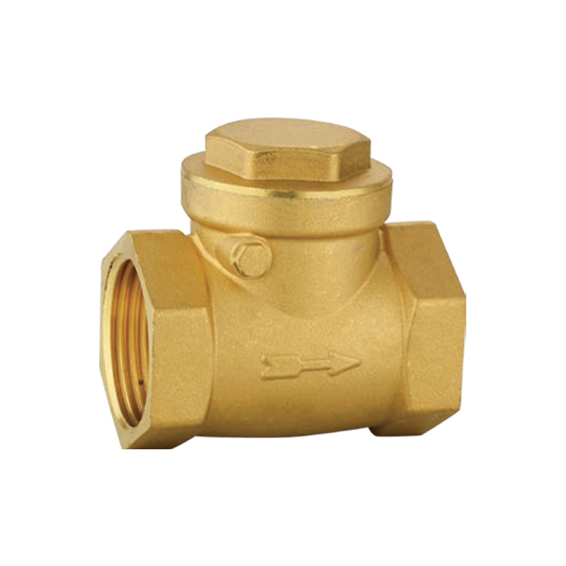
Flow Direction Verification — The arrow cast on the brass body indicates the forward flow direction. Installing the valve backward results in no flow (fully closed) or reduced flow (if the disc moves partially). For spring-loaded checks, reverse installation allows forward flow, but the spring holds the disc closed — flow occurs only at pressures exceeding the spring rate, creating a pressure drop of 1-3 bar. After installation, test by applying forward pressure (0.5-1 bar) and listening for the disc opening (click sound). No sound suggests incorrect orientation. Use a flow meter to confirm the expected flow rate. Reversing a valve after application of pressure damages the seat because reverse pressure drives the disc against the seat in the wrong direction.
Debris Protection Before Installation — Brass check valves are supplied clean, but pipe systems contain debris: metal shavings from threading, Teflon tape fragments, solder beads, and rust particles. Install a strainer (mesh 40 or finer) upstream of the check valve during system start-up. After flushing the system for 5-10 minutes at full flow, remove the strainer. A 1 mm debris particle lodged between the disc and seat prevents sealing, causing reverse flow. For swing checks, debris trapped under the seat ring produces leakage of 1-5 percent of the forward flow rate. For ball checks, debris holds the ball off the seat, creating continuous leakage. Inspect the valve interior before installation by shining a light through the outlet port.
Pipe Thread Sealant Application — Use PTFE tape (3-5 wraps) or pipe joint compound (liquid or paste). Do not allow tape or compound to enter the valve interior. Excess tape wraps beyond the first three threads are trimmed by pipe engagement and pushed into the valve. This debris adheres to the disc and seat. Apply tape only to the male threads, stopping one thread short of the pipe end. For a liquid compound, apply a thin coat (0.5-1 mm) only to the middle threads. Do not apply to the first thread. Tighten brass fittings with two wrenches: one on the valve body, one on the pipe. Tightening by turning the valve body alone applies torque to internal connections, loosening the bonnet or seat ring.
Orientation for Different Types — Swing check valves require horizontal installation with the hinge pin vertical (disc swings upward). Installing a swing check vertically (pipe vertical, flow upward) is possible, but the disc may not fully open at low flow rates (below 0.5 m/s velocity). Spring-loaded inline checks and ball checks operate in any orientation because the spring or ball weight is symmetric. Lift checks (piston type) must be installed horizontally with the bonnet on top. Installing a lift check upside down (bonnet below) allows the piston to fall off the seat under gravity, blocking flow even in the forward direction. Check the manufacturer's data sheet for orientation-specific models.
Water Hammer Prevention — Swing check valves close rapidly when flow stops, generating pressure spikes (water hammer) of 5-20 times normal pressure. A water hammer of 20 bar in a 10 bar system can burst downstream pipes or damage pumps. Install a slow-closing silent check valve or add a spring-assist to the swing disc. Alternatively, install a water hammer arrestor within 1 meter of the check valve. For existing systems experiencing water hammer, replace swing checks with spring-loaded inline checks. The spring closes the disc before reverse flow develops, reducing pressure spike amplitude by 70-90 percent.
Temperature Limits for Elastomers — Standard NBR seals fail above 100°C. At 110°C, NBR hardens within 10 hours and cracks. For hot water heating systems (80-95°C), NBR is acceptable. For steam lines (100-180°C), use EPDM or PTFE seats. For steam above 180°C, use metal seats only (no elastomers). For cold systems below -20°C (outdoor installations), NBR becomes brittle and fractures when the disc strikes the seat. Use FKM or silicone rubber for low-temperature applications (down to -50°C). Check the valve's temperature rating on the body; a designation "WSP" (Working Steam Pressure) indicates 180°C rating; "WOG" (Water, Oil, Gas) indicates a 38-80°C rating depending on material.
Periodic Leak Testing — Test check valves annually or after a system shutdown. Isolate the valve by closing upstream and downstream shutoff valves. Open a drain downstream to depressurize the line. Apply upstream pressure (50-75 percent of system pressure). Listen at the downstream side with a mechanic's stethoscope or use a leak detection spray (soap solution). Bubbles indicate reverse leakage. For quantitative measurement, install a temporary flow meter downstream. Acceptable leakage rates per ANSI/FCI 70-2: Class II allows 0.5-1 percent of full flow; Class IV allows 0.01-0.05 percent. Leakage above Class II requires seat replacement or lapping.
Corrosion Monitoring in Aggressive Water — Brass check valves in water with a pH below 6.5 or above 8.5 experience dezincification. Signs include: white powdery deposits (zinc oxide) on the body, pitting visible under bright light, and reduced thickness of the seat ring. Dezincification weakens the brass: tensile strength drops from 330 MPa to below 150 MPa after one year in aggressive water. Replace valves when the body wall thickness at the seat area is reduced by 20 percent. Use DZR brass (C35200 or C46500) for water with a pH below 6.5, high chloride (>250 ppm), or water temperatures above 60°C. Do not use standard brass (C84400 or C37700) in swimming pool water containing chlorine (1-5 ppm residual), as dezincification occurs within 6-12 months. Replace DZR valves every 5-7 years as preventative maintenance.
Freeze Protection — Water trapped in a brass check valve expands when frozen, cracking the body. A 1-inch brass body cracks when ice forms if water cannot expand into an open pipe. Install drain ports upstream and downstream of the valve. Before freezing weather, close the upstream shutoff, open the drain, and blow compressed air (0.5-1 bar) through the valve to remove water. For valves that cannot be drained, wrap with electric heat tape (self-regulating type, 10-20 W/m) and insulate. Do not use antifreeze (propylene glycol) in potable water systems unless rated for drinking water. Antifreeze additives degrade NBR seals, causing swelling (10-20 percent volume increase) and loss of sealing force.
Conact Us Anytime.
-
Email us
kyoda@kyodavalve.com
-
Call us
+86-19105861791