English
 русский
 Español
 عربى
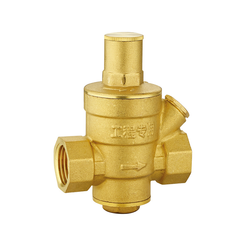
عربىApplication Considerations for Brass Pressure Reducing Valves
System Sizing and Pressure Selection
The proper application of a brass pressure reducing valve (PRV) begins with accurate determination of system parameters. Incorrect sizing is a common cause of poor performance, including pressure instability, premature wear, and inadequate flow delivery. The selection process must account for inlet pressure range, desired outlet pressure, flow requirements, and the characteristics of downstream fixtures and appliances.
Inlet pressure is the first parameter to establish. Brass PRVs are typically rated for inlet pressures ranging from 150 to 300 pounds per square inch (psi), with standard residential models commonly rated at 150 to 200 psInlet pressure should be measured under both static (no flow) and dynamic (flowing) conditions, as pressure fluctuations can affect valve performance. Systems with inlet pressures exceeding the valve's rating require either a higher-rated valve or a two-stage reduction configuration. Prolonged operation at pressures above the valve's rating can cause internal component fatigue, seat damage, or failure of the spring mechanism.
Installation Requirements and Positioning
Proper installation of brass pressure reducing valves directly affects their operational reliability and service life. The installation process involves considerations of orientation, upstream treatment, bypass provisions, and accessibility for maintenance. Deviations from recommended practices can lead to premature failure or unsatisfactory performance.
Orientation is typically specified by the manufacturer, with brass PRVs designed for installation in a horizontal position with the adjustment screw facing upward. This orientation ensures that the internal spring mechanism operates as designed and that the valve does not trap debris or sediment in critical areas. Installing a PRV in a non-standard orientation—such as vertically or inverted—may alter the valve's pressure setting or cause the internal components to bind. Some manufacturers offer valves specifically designed for vertical installation; these should be selected when horizontal orientation is not feasible.
Upstream filtration represents a critical installation consideration. Brass PRVs contain internal passages, seats, and diaphragms that can be damaged by sediment, scale, or debris carried in the water supply. Installing a Y-strainer or basket strainer upstream of the PRV, with a mesh size of 40 to 100 mesh depending on water quality, captures particulate matter before it can enter the valve. For systems with known sediment issues, a blow-down strainer with a flush valve allows periodic cleaning without system shutdown. The strainer should be installed with a pressure gauge on both the inlet and outlet sides to monitor pressure drop across the strainer, indicating when cleaning is required.
Bypass provisions allow system operation during valve maintenance or failure. In critical applications where uninterrupted water supply is essential, a bypass line with isolation valves permits water to flow around the PRV when the valve is removed or serviced. The bypass line should include its own isolation valve and, if necessary, a temporary pressure regulating device to prevent excessive pressure from reaching downstream fixtures. For residential applications, bypass piping is less common, but installing full-port isolation valves upstream and downstream of the PRV facilitates valve replacement without draining the entire system.
Water Quality and Environmental Factors
The performance and longevity of brass pressure-reducing valves are significantly influenced by the quality of the water passing through them and the environmental conditions in which they operate. Water chemistry, temperature, and the presence of aggressive agents all affect the valve's internal components and sealing surfaces.
Water hardness presents a common challenge. Hard water—containing elevated levels of calcium and magnesium carbonates—can deposit scale on internal valve components, particularly on the seat and diaphragm surfaces. Scale accumulation interferes with the valve's ability to seal completely, resulting in creep (gradual pressure rise under no-flow conditions) or continuous leakage. In regions with hard water, installing a water softener upstream of the PRV reduces scale formation. Where softeners are not installed, valves with larger internal passages and self-cleaning designs may provide better service life, though periodic disassembly and cleaning remain necessary.
Environmental factors external to the water system also affect valve performance. Brass PRVs installed in unconditioned spaces—such as basements, crawl spaces, or outdoor enclosures—are subject to temperatures that can affect internal components. Freezing temperatures present the greatest risk; water trapped within the valve can freeze and expand, cracking the brass body or damaging internal components. Valves installed in areas subject to freezing must be protected with insulation, heat tape, or located within conditioned spaces. High ambient temperatures, particularly in mechanical rooms with heating equipment, can accelerate the aging of elastomeric seals and reduce the effective spring force of the internal spring.
Maintenance, Adjustment, and Failure Indicators
Brass pressure-reducing valves require periodic maintenance and monitoring to ensure continued proper operation. Unlike many plumbing components that operate without intervention, PRVs contain moving parts and sealing surfaces that wear over time. Establishing a maintenance schedule and recognizing indicators of developing problems extends service life and prevents sudden failure.
Periodic testing and verification should be performed at intervals of 12 to 24 months, depending on water quality and usage. Testing involves measuring static pressure (with no downstream flow) and dynamic pressure (with fixtures operating) at the valve outlet. Static pressure should remain stable at the set point; a gradual increase indicates seat wear or debris interfering with the valve's ability to close fully. Dynamic pressure should not drop excessively below the set point during peak flow; a significant pressure drop suggests either valve undersizing or internal wear limiting flow capacity.
Conact Us Anytime.
-
Email us
kyoda@kyodavalve.com
-
Call us
+86-19105861791